If you are reading this, then you probably want to know more about stepper motors. I will start at the basics and work my way up. I am going to be referring to the permanent magnet 2 phase variety. Other stepper motors exist but are beyond the scope of this article. A stepper motor is a brushless DC motor that is made to turn a fraction of a turn at a time. This means that the stepper motor is ideal for use in CNC machines (like the RepRap, Makerbot, Ultimaker etc) as the small steps – hence the name – allow for greater precision that is possible with standard DC motors. That is to say that the stepper motor can be controlled using an open-loop controller, as the step size is more or less constant and the motor shouldn’t slip – assuming the stepper is driven correctly.
If you have bought the stepper motor then chances are you already know quite a bit about its characteristics. If not there are some simple calculations and experiments to specify its performance.
Identifying Your Stepper
Not only do stepper motors come in a variety of shapes and sizes, they also have different coil configurations. This can help identify how to drive the stepper motor, and what sort of controller you are likely to need to drive the motor. Stepper motors typically have 4,5,6 or 8 wires, and these can be used to identify the type of motor. There are two types of stepper; Unipolar and Bipolar. This refers to how each coil is driven. A unipolar stepper only requires each coil to be driven in one direction, whereas a bipolar requires driving in both directions. Unipolar motors achieve this by each coil having a centre tap. Using a DMM, test each combination of wires. Each coil should have similar DC resistances, so this is a simple way of testing coil integrity. By working your way through the wire combinations it is possible to identify each coil (equal resistances), and if a centre-tap is used (half the resistance of a full coil). Generally a 4 wire stepper is bipolar and anything greater is unipolar.
Does It Work?
So you have left your DMM at home but want to test the stepper motor anyway. A very simple check of the coil integrity is to short either end of the coil together and try to turn the shaft. I wont go into Lenz’s Law, but basically by shorting the coil together you are apposing the generation of an EMF, and by extension the stepper will be harder to turn.
Characterising the Stepper
Firstly, you might want to know the resolution of the stepper. This is measured in degrees per step, with typical values ranging from 1.8deg to 7.5deg (or 200 to 48 steps per complete revolution). Obviously a smaller step size is preferable as it allows for greater resolution. Shorting out the coil, and counting the amount of times the stepper stalls when turning manually will give a value half that of the total number of steps in a complete revolution. Another method would be to build a controller and count the number of pulses needed to perform one rotation – however this requires a driver circuit.
The following are rules-of-thumb, and should be treated as such. There is every possibility that you can burn out the stepper coil, but you should be alright if you keep a close eye.
Coil inductance is useful to know as this dictates the maximum voltage the coil is likely to take. This can be measured by putting the coil in series with a known resistor (typically 100R to 1K), and exciting the circuit with a function generator (between 2kHz and 10kHz). Using the frequency, known resistor value, coil DC resistance, function generator output voltage, and the voltage , it is possible to calculate the coils reactance and thus inductance.

Maximum voltage is then 1000*sqrt(L). One of the motors I used these equations on gave a coil inductance of 0.00338H, and so a maximum voltage of 58volts. Given the coil resistance was only 1.6ohms, I would need 36A per phase, or 72A in total. This would obviously give me a very hot motor, and probably burn the coils out.
Most stepper motors are built to withstand an 80°C rise in temperature. Personally, I would reduce the voltage or current such that the stepper did not get that hot.
Another important bit of information you might want to know is the holding torque. This is the ability of the motor to remain stationary when under an external load. The following experiment might well leave you feeling like a school child but bear with me as communities responsible for open source 3d printers specify particular holding torque values. First you energise the coils in one of the modes of operation mentioned later, and then you suspend a weight from a arm of a particular length. The RepRap recommends a 13.7N-cm stepper, which corresponds to roughly 1.4kg suspended on an arm 1cm long. That is to say if your motor doesn’t move when loaded with a 1.4kg weight on an arm 1cm long then it has a holding torque of at least 13.7N-cm.
Modes of Operation
There are three simple ways of driving a stepper motor; full step, half step and wave drive. A forth method called micro-stepping exists, but this is beyond the scope of this article, and has the disadvantage of having unpredictable and unrepeatable step sizes.
- Full stepping is when two coils are always energised at the same time. This allows the maximum torque of the motor to be used, at the expense of more current.
- Half stepping is achieved by alternating between energising a single coil and two coils at the same time. This increases the angular resolution, but the torque fluctuates between utilising a single coil and both coils.
- Wave driving is the least useful as only one coil is on at any one time. Although this allows less current to be used, it also produces the least amount of torque.
Stepper Circuits
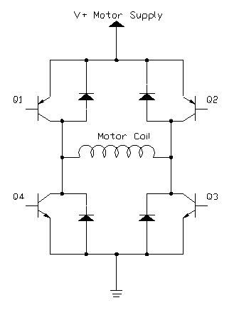
With bipolar motors you have to create an H-bridge circuit. The H-b ridge consists of 4 transistors (2 NPN and 2 PNP) switched in pairs (Q1 and Q3, Q2 and Q4) such that current can flow through the coil. H-bridges are used in the control on normal DC motors to achieve forward and reverse movement. Fly-back diodes are included to protect the transistors from inductive kick-back; that is the inductive spike generated when switching the coil off. As we have two coils, then 2 of these circuits will be needed. It might also be necessary to use Darlington pairs instead of transistors purely because of the current load. One extra thing to be aware of is that if Q1 and Q4 are on at the same time (due to the switching characteristics of the transistor) then you will be shorting out the power rails. Optimisations can be made to this circuit by switching Q1 and Q3 with an additional transistor as this will half the amount of IO needed.
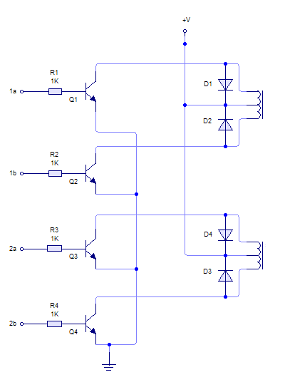
Unipolar motors can be driven with a single transistor for  each coil. Again, fly-back diodes are included to protect the transistors. Clearly this is a much simpler driver circuit, but can only be used for unipolar motors. This simple circuit has its own trade-offs; only half the coil is energised at any one time, and as such the amount of torque generated is less. I prefer to ignore the centre tap, and drive the unipolar motor as a bipolar motor. Granted the circuit contains a greater number of components, but you get more torque and ultimately the circuit differences are forgotten when working in software.
Driving the Stepper
At this point I have to leave you. This article is getting longer that I had hoped for, and so stay tuned for some information on the actual drive circuitry needed to efficiently (and not so efficiently) get your steppers moving. If you are desperate to get started then feel free to breadboard up those circuits already shown, but be wary of the current capacity of the switching devices and your power supply.